To be a valuable global supplier
for metallic honeycombs and turbine parts


Contact number
0555-2813555
To be a valuable global supplier
for metallic honeycombs and turbine parts
Technological Innovation
Process Management
Continuous Improvement
Customer Satisfaction

Knowledge
Dedication
Diligence
Loyalty
Responsibility
Confidence
Tenacity
Respect
To be a valuable global supplier
for metallic honeycombs and turbine parts
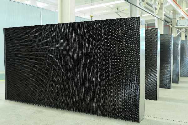
MAT Aviation manufactures metallic honeycomb flow straighteners for wind tunnel and water tunnel projects. Formed and welded honeycomb structures can be customized in cell size, foil thickness, core depth and overall dimensions according to customer drawings.
MAT Aviation has many years of experience manufacturing honeycomb flow straighteners for wind tunnel applications. Our project experience includes aerodynamic testing facilities serving internationally recognized automotive and aerospace manufacturers, as well as specialist testing and research organizations. Customer identities and project details are treated as confidential.
The parallel channels help reduce swirl and transverse airflow components, guiding flow more closely along the tunnel axis. Honeycomb is commonly used with screens in the settling chamber. Test-section flow quality also depends on the screens, contraction, installation and operating conditions.
| Product Feature | Available Scope |
|---|---|
| Large individual modules | Maximum individual module size: 3 x 3 m, depending on the selected configuration. |
| Custom core geometry | Cell size, foil thickness and core depth are reviewed together against the project drawing and flow-conditioning requirements. |
| Formed and welded metal structure | Honeycomb cells are assembled from formed metal strips and joined by welding. |
| Drawing-based supply | Overall shape, module arrangement, frame requirements and mounting interfaces can be submitted for engineering review. |
Our honeycomb flow straighteners are primarily manufactured from stainless steel and aluminum. Other materials can be considered for custom applications, subject to project requirements and technical review.
Supply requirements may cover honeycomb cores, panels or individual modules. Frame and mounting-interface requirements should be identified on the drawing and confirmed in the agreed supply scope.
Manufacturing combines strip forming, honeycomb assembly, welding and dimensional inspection. Project inspection requirements can cover cell dimensions, core depth, overall module size, channel alignment, parallelism, joint condition and material traceability.
Where yaw and pitch angle verification is required, the measurement method, test locations, operating conditions and acceptance criteria should be defined for the project.
MAT Aviation operates an AS9100D-certified quality management system. Inspection documentation and applicable process requirements are confirmed against the order scope.
| Application | Product Role |
|---|---|
| Aerospace and automotive wind tunnels | Honeycomb modules for the settling-chamber flow-conditioning section. |
| University and research wind tunnels | Custom core dimensions and module layouts for aerodynamic research facilities. |
| Water tunnels | Honeycomb configurations evaluated for the specified liquid medium, corrosion conditions and mounting arrangement. |
Engineering reading: How honeycomb flow straighteners support wind tunnel testing.
The tables below list standard core and large cell configurations. Maximum dimensions refer to one individual module.
| Cell Size D (mm) | Foil Thickness (mm) | Core Depth L (mm) | L/D | Max. Module Size |
|---|---|---|---|---|
| 10 | 0.15 | 100 | 10 | 2 x 2 m |
| 150 | 15 | |||
| 200 | 20 | |||
| 280 | 28 | |||
| 12.7 | 115 | 9.06 | ||
| 160 | 12.6 | |||
| 240 | 18.9 | |||
| 15 | 150 | 10 | ||
| 200 | 13.33 | |||
| 225 | 15 | |||
| 16 | 0.20 | 240 | 15 | |
| 260 | 16.25 | |||
| 320 | 20 | |||
| 600 | 37.5 | |||
| 25 | 360 | 14.4 | ||
| 500 | 20 | |||
| 30 | 300 | 10 | ||
| 450 | 15 | |||
| 42 | 420 | 10 |
Specific dimensions and shapes can be customized to your requirements.
Each row lists one core depth and its corresponding L/D value.
| Cell Size D (mm) | Foil Thickness (mm) | Core Depth L (mm) | L/D | Max. Module Size |
|---|---|---|---|---|
| 10 | 0.15 | 100 | 10 | 3 x 3 m |
| 150 | 15 | |||
| 200 | 20 | |||
| 12.7 | 115 | 9.06 | ||
| 160 | 12.6 | |||
| 240 | 18.9 | |||
| 15 | 150 | 10 | ||
| 200 | 13.33 | |||
| 225 | 15 | |||
| 16 | 0.20 | 240 | 15 | |
| 260 | 16.25 | |||
| 320 | 20 | |||
| 600 | 37.5 | |||
| 20 | 200 | 10 | ||
| 300 | 15 | |||
| 400 | 20 | |||
| 420 | 21 | |||
| 25 | 0.25 | 360 | 14.4 | |
| 500 | 20 | |||
| 30 | 300 | 10 | ||
| 450 | 15 | |||
| 38 | 550 | 14.47 | ||
| 750 | 19.74 | |||
| 42 | 0.30 | 420 | 10 |
Specific dimensions and shapes can be customized to your requirements.
D - Cell size: The nominal single-cell dimension shown in the table. The measurement convention is specified on the project drawing.
Foil thickness: The thickness of the metal strip forming the honeycomb walls.
L - Core depth: The channel length along the airflow direction. L/D is calculated from the listed nominal dimensions and rounded to two decimal places if needed.
The dimensions in each row form a specific configuration. Material, module size, mounting details and acceptance criteria are confirmed on the approved project drawing.
Can the dimensions be customized?
Cell size, foil thickness, core depth and overall dimensions can be reviewed against your drawing and technical requirements.
Does 3 x 3 m mean the size of one module?
Yes. 3 x 3 m is the maximum individual module size for the applicable configuration.
How is the L/D ratio specified?
The L/D ratio depends on the tunnel design, inlet flow, allowable pressure loss and installation space.
Please send your drawing, material grade, cell size, foil thickness, core depth, overall module dimensions and quantity. Include frame requirements, operating conditions and inspection criteria for your project.
Email: mat@mat-cm.com